Inductors, Faraday's law and transformers
What this lesson covers
- Magnetic flux φ = BA measures the field passing through an area; flux density B, in tesla, is flux per square metre.
- Faraday's law: the induced EMF equals the rate of change of flux linkage, ε = −N Δφ ÷ Δt.
- Lenz's law: the induced current flows so that its magnetic field opposes the change that caused it, which keeps energy conserved.
- An inductor opposes changes in its own current with a back EMF ε = −L ΔI ÷ Δt; in an LR circuit the current grows with time constant τ = L ÷ R, and the energy stored is ½LI².
- A transformer uses a changing current in one coil to induce an EMF in another, with Vp ÷ Vs = Np ÷ Ns.
Magnetic flux and flux density
- Magnetic flux φ is the amount of magnetic field passing through an area: φ = BA when the field is at right angles to the area, measured in webers (Wb).
- Flux density B is the flux per unit area, measured in tesla, where 1 T = 1 Wb m⁻²; it is the B you already use in F = BIL.
- If the area is tilted so the field is not perpendicular, only the perpendicular component of B counts, so the flux is smaller.
- A coil of N turns has flux linkage Nφ, because the same flux passes through every turn.
Faraday's and Lenz's laws
- Faraday's law: an EMF is induced in a coil whenever the flux through it changes, equal to the rate of change of flux linkage: ε = −N Δφ ÷ Δt.
- The flux can change because the field changes, the area changes, or the coil moves or turns; a steady flux, however strong, induces nothing.
- Lenz's law (the minus sign): the induced current creates a magnetic field that opposes the change in flux. Push a north pole in and the coil's near end becomes a north pole, pushing back.
- If the induced current helped the change instead, it would increase without limit and create energy from nothing, so Lenz's law is energy conservation: you must do work against it.
Try it: induce a voltage
Example: switching off an electromagnet
- A 150-turn coil of area 2.50 × 10⁻³ m² sits at right angles to a 0.800 T field. The field falls steadily to zero in 0.0500 s.
- Find the change in flux and the average induced EMF.
- φ = BA = 0.800 × 2.50 × 10⁻³ = 2.00 × 10⁻³ Wb at the start, 0 at the end
- Δφ = 0 − 2.00 × 10⁻³ = −2.00 × 10⁻³ Wb
- ε = −N Δφ ÷ Δt = −150 × (−2.00 × 10⁻³) ÷ 0.0500 = 6.00 V
- units: Wb s⁻¹ = T m² s⁻¹ = V
- Δφ = 2.00 × 10⁻³ Wb; ε = 6.00 V, driving a current that tries to keep the flux
Inductors and self inductance
- A current in a coil makes a magnetic flux through the coil itself, so changing the current changes that flux and induces an EMF in the same coil.
- By Lenz's law this back EMF opposes the change in current: ε = −L ΔI ÷ Δt, where L is the self inductance in henrys (H).
- An inductor only opposes changes; with a steady current, there is no induced EMF and only the coil's resistance matters.
- More turns, a larger area and an iron core all raise L, because they make more flux linkage for each ampere.
Current and voltage in an LR circuit
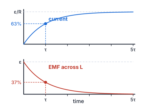
- When the switch closes, the current starts at zero: if it jumped, ΔI ÷ Δt would be infinite. So at first the whole supply voltage is across the inductor, and the current starts rising at a rate ε ÷ L.
- As the current grows, the resistor takes more of the voltage (IR), the inductor less, so the current rises more and more slowly towards ε ÷ R.
- The time constant is τ = L ÷ R: after one τ the current reaches 63% of its final value and the inductor's EMF falls to 37% of ε.
- When the circuit is broken, the current tries to fall to zero almost instantly, so ΔI ÷ Δt is huge and so is the induced EMF; it can make a spark jump across the opening switch.
Try it: current growth in an LR circuit
Example: an inductor switched on
- A 0.400 H inductor with a total circuit resistance of 8.00 Ω is connected to a 12.0 V battery of negligible internal resistance.
- Find the time constant, the final current, the current and inductor EMF after one time constant, and the energy stored at the final current.
- τ = L ÷ R = 0.400 ÷ 8.00 = 0.0500 s
- I_final = ε ÷ R = 12.0 ÷ 8.00 = 1.50 A
- after τ: I = 0.632 × 1.50 = 0.948 A
- V_R = 0.9482 × 8.00 = 7.59 V, so V_L = 12.0 − 7.59 = 4.41 VKirchhoff's voltage law round the loop
- 0.368 × 12.0 = 4.41 V agrees
- E = ½LI² = ½ × 0.400 × 1.50² = 0.450 J
- 0.0500 s; 1.50 A; 0.948 A and 4.41 V; 0.450 J
Transformers
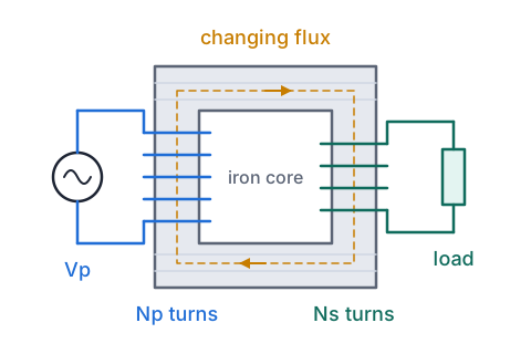
- A transformer has two coils wound on one iron core. An alternating current in the primary makes a changing flux in the core, which passes through the secondary and induces an alternating EMF there.
- Every turn has the same changing flux, so the voltages are in the ratio of the turns: Vp ÷ Vs = Np ÷ Ns. More secondary turns step the voltage up; fewer step it down.
- An ideal transformer wastes no energy, so VpIp = VsIs: stepping the voltage up steps the current down by the same factor.
- It only works with AC, because a steady current gives a steady flux and no induced EMF.
- Real cores are laminated (thin insulated sheets) to cut eddy currents, the currents Faraday's law induces in the core itself, which would waste energy as heat.
Example: from the street transformer to the grid
- A street transformer steps 11.0 kV down to 230 V and supplies 100 kW to a group of houses. Treat it as an ideal single-phase transformer.
- Find the turns ratio and both currents. Then compare the power lost in 2.00 Ω of line when 100 MW is sent at 220 kV, as on Transpower's main lines, and at 11.0 kV.
- Np ÷ Ns = Vp ÷ Vs = 11 000 ÷ 230 = 47.8
- Is = P ÷ Vs = 100 000 ÷ 230 = 435 A; Ip = P ÷ Vp = 100 000 ÷ 11 000 = 9.09 A
- Ip ÷ Is = 9.09 ÷ 435 = 1 ÷ 47.8, the inverse of the voltage ratio
- at 220 kV: I = 1.00 × 10⁸ ÷ 2.20 × 10⁵ = 455 A, loss = I²R = 454.5² × 2.00 = 4.13 × 10⁵ W
- at 11.0 kV: I = 9091 A, loss = 9091² × 2.00 = 1.65 × 10⁸ W, more than the power being sent
- ratio 47.8; 9.09 A and 435 A; 0.413 MW lost at 220 kV against 165 MW at 11.0 kV
What Achieved, Merit and Excellence look like
- Achieved names the law or the effect; Merit explains it with a changing flux and an opposing current; Excellence links the flux change, the induced current's field, the force and the energy.
- In Lenz's law answers, say what is changing, which way the induced field points, and what that does.
| Grade | A model answer |
|---|---|
| Achieved | The moving magnet induces currents in the copper pipe, which slow it down. |
| Merit | As the magnet falls, the flux through each ring of the pipe changes, so an EMF and a current are induced. By Lenz's law these currents make magnetic fields that oppose the change, so they repel the magnet from above and attract it from below, slowing it. |
| Excellence | The falling magnet changes the flux through the rings of copper below it (increasing) and above it (decreasing), inducing eddy currents by Faraday's law. By Lenz's law the field of the ring below repels the magnet and the ring above attracts it, both forces acting upward. The faster it falls, the faster the flux changes and the larger the force, so it quickly reaches a slow terminal speed. Its lost gravitational energy becomes heat in the copper rather than kinetic energy. |
Common mistakes
- A strong magnet sitting still inside a coil induces a large EMF.Only a changing flux induces an EMF; a stationary magnet in a stationary coil induces nothing.
- When the switch closes, the current jumps to ε ÷ R and the inductor's voltage is zero.At the instant of closing the current is zero and the inductor has the full supply voltage; the current then rises with τ = L ÷ R.
- A step-up transformer gives you more power, because the voltage goes up.At best power out equals power in, so when the voltage steps up, the current steps down.
- A transformer connected to a car battery will step 12 V up to 230 V.A steady DC current makes no changing flux, so a transformer gives no output from DC.
Read the transformer labels on old chargers
You need: unplugged chargers and power adaptors, paper and a pen, a calculator, a kitchen scale
- Gather every unplugged charger and power adaptor you can find, and read the input and output lines on each label.
- Sort them into ones whose output says AC (a plain transformer inside) and ones whose output says DC.
- For each AC one, work out the turns ratio Np ÷ Ns = Vin ÷ Vout, and the input current an ideal transformer would need at the rated output (Iin = Vout × Iout ÷ Vin).
- Compare that with the input current printed on the label, and weigh a heavy old adaptor against a light modern phone charger.
- Look for: the label's input current is larger than the ideal value, because real transformers lose energy as heat; and the old heavy adaptors hold a big iron core, while modern chargers switch at high frequency so a tiny core does the same job.
Safety: Only handle chargers that are unplugged at the wall, and never open their cases, because capacitors inside some adaptors can hold a dangerous charge even after unplugging.
Your turn
A 0.250 T field passes at right angles through a loop of area 0.0400 m². Find the flux.
That flux falls to zero in 0.100 s through a 500-turn coil. Find the average induced EMF.
The current in a 0.200 H inductor changes at 30.0 A s⁻¹. Find the size of the back EMF.
A transformer has 920 primary turns on a 230 V supply. How many secondary turns give 10.0 V, and what is the primary current when the secondary supplies 2.30 A, if it is ideal?
Show answer
1. φ = BA = 0.250 × 0.0400 = 0.0100 Wb. 2. ε = N Δφ ÷ Δt = 500 × 0.0100 ÷ 0.100 = 50.0 V. 3. ε = L ΔI ÷ Δt = 0.200 × 30.0 = 6.00 V. 4. Ns = Np × Vs ÷ Vp = 920 × 10.0 ÷ 230 = 40 turns; Ip = VsIs ÷ Vp = 10.0 × 2.30 ÷ 230 = 0.100 A.
Exam-style question: a coil on a battery
- A large coil has an inductance of 2.50 H and a resistance of 5.00 Ω. It is connected through a switch to a 10.0 V battery of negligible internal resistance.
Calculate the final current and the time constant.
Calculate the rate at which the current starts to increase, and explain why the current does not jump straight to its final value.
Calculate the EMF across the inductor 0.300 s after the switch is closed.
Calculate the energy stored once the current is steady, and explain why a large voltage appears across the switch when it is opened.
Show answer
1. I = ε ÷ R = 10.0 ÷ 5.00 = 2.00 A; τ = L ÷ R = 2.50 ÷ 5.00 = 0.500 s (Achieved). 2. At the instant of closing I = 0, so there is no voltage across the resistance and the inductor has all 10.0 V: ΔI ÷ Δt = ε ÷ L = 10.0 ÷ 2.50 = 4.00 A s⁻¹. The growing current makes a growing flux in the coil, which induces a back EMF opposing the increase (Lenz's law), so the current can only rise gradually (Merit). 3. V_L = ε e^(−t ÷ τ) = 10.0 × e^(−0.300 ÷ 0.500) = 10.0 × 0.549 = 5.49 V (Excellence; 0.300 s is less than one τ, so more than 37% of 10.0 V is sensible). 4. E = ½LI² = ½ × 2.50 × 2.00² = 5.00 J. Opening the switch makes the current fall to zero in a very short time, so the flux through the coil collapses very quickly. The induced EMF, L ΔI ÷ Δt, is very large and, by Lenz's law, acts to keep the current flowing; it appears across the opening switch contacts, and much of the 5.00 J stored in the magnetic field is released in the spark (Excellence links the rapid change, the size of the EMF and the stored energy).
Faraday's Law
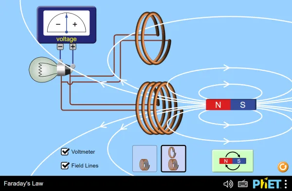
Full screen · PhET Interactive Simulations, University of Colorado Boulder, CC BY 4.0
Recap
- φ = BA, in webers; B is in tesla.
- ε = −N Δφ ÷ Δt: only a changing flux induces an EMF, and Lenz's law makes it oppose the change.
- An inductor's back EMF is −L ΔI ÷ Δt, so current in an LR circuit grows with τ = L ÷ R.
- Energy stored in an inductor is ½LI², released when the current stops.
- Transformers need AC: Vp ÷ Vs = Np ÷ Ns and, if ideal, VpIp = VsIs.
| Formula | Use it for |
|---|---|
| φ = BA | magnetic flux |
| ε = −N Δφ ÷ Δt | induced EMF in a coil |
| ε = −L ΔI ÷ Δt | back EMF in an inductor |
| τ = L ÷ R, E = ½LI² | LR time constant and stored energy |
| Vp ÷ Vs = Np ÷ Ns | transformers |
Report a mistake
How is NCEA Level 3 maths going?
See the NCEA Level 3 maths guide