AC circuits
What this lesson covers
- An AC voltage varies as V = V_max sin ωt; its rms value, V_max ÷ √2, is the steady DC voltage that would give the same heating in a resistor.
- In a resistor the current and voltage are in phase; in an inductor the voltage leads the current by 90°, and in a capacitor the current leads the voltage by 90°.
- Reactance X_L = ωL rises with frequency and X_C = 1 ÷ (ωC) falls with frequency; V = IX for each component.
- In a series circuit the voltages add as phasors, giving the impedance Z = √(R² + (X_L − X_C)²) and V = IZ.
- A series LCR circuit resonates when X_L = X_C, at f₀ = 1 ÷ (2π√(LC)), where the impedance is smallest and the current largest.
Peak and rms values
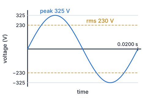
- An alternating voltage changes as V = V_max sin ωt, with ω = 2πf. New Zealand's mains supply has f = 50 Hz, so one cycle takes 0.0200 s.
- The power in a resistor, I²R, is always positive but varies through the cycle; its average is half the peak power.
- The rms (root mean square) value is the steady DC value that would give the same average power: V_rms = V_max ÷ √2 and I_rms = I_max ÷ √2.
- Mains '230 V' is an rms value, so the peak is 230 × √2 = 325 V. Meters read rms, and P = V_rms I_rms for a resistor.
Example: a 2.00 kW jug
- An electric jug is rated at 2.00 kW on 230 V rms mains.
- Find the rms and peak currents, the element's resistance and the peak power.
- I_rms = P ÷ V_rms = 2000 ÷ 230 = 8.70 A
- I_max = √2 × 8.70 = 12.3 A
- R = V_rms ÷ I_rms = 230 ÷ 8.696 = 26.5 Ω
- peak power = V_max I_max = 325 × 12.3 = 4.00 kW, twice the averagethe average of sin² over a cycle is ½
- R = V² ÷ P = 230² ÷ 2000 = 26.45 Ω agrees
- 8.70 A rms, 12.3 A peak, 26.5 Ω, 4.00 kW peak
Phase in resistors, inductors and capacitors
- In a resistor V = IR at every instant, so the voltage and current peak together: they are in phase.
- An inductor's voltage depends on how fast the current changes, which is fastest as the current passes through zero. So the inductor's voltage peaks a quarter cycle before the current: V_L leads I by 90°.
- A capacitor's current is greatest when its voltage is changing fastest, as the voltage passes through zero. So I leads V_C by 90°.
- Phasors show this: draw each quantity as a rotating arrow, take the current as the reference along the x axis, then V_R lies along it, V_L points straight up and V_C straight down.
Try it: shift the current's phase
Reactance and impedance
- Reactance X is the opposition of an inductor or capacitor to AC, in ohms, with V = IX (both rms or both peak).
- X_L = ωL: at higher frequency the current changes faster, the back EMF is bigger, so the inductor lets less current through.
- X_C = 1 ÷ (ωC): at higher frequency the capacitor charges and discharges more times a second, moving more charge, so more current flows.
- In a series circuit the same current flows through everything, but the voltages peak at different times, so they add as phasors: V² = V_R² + (V_L − V_C)².
- Dividing by I gives the impedance, Z = √(R² + (X_L − X_C)²), with V = IZ and the phase angle between supply voltage and current from tan φ = (X_L − X_C) ÷ R.
Example: an LR series circuit
- A 120 Ω resistor and a 0.500 H inductor (with negligible resistance) are in series with a 12.0 V rms, 50.0 Hz supply.
- Find the reactance, the impedance, the current, the voltage across each component and the phase angle.
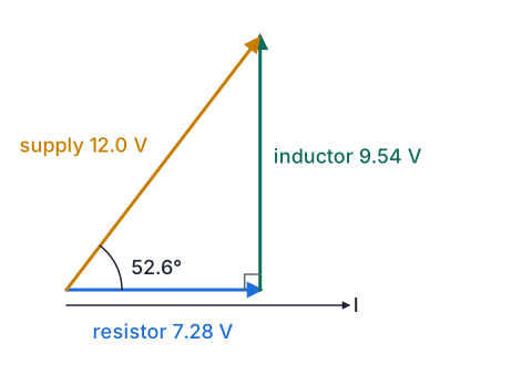
- X_L = 2πfL = 2π × 50.0 × 0.500 = 157 Ω
- Z = √(120² + 157.1²) = 198 Ω
- I = V ÷ Z = 12.0 ÷ 197.7 = 0.0607 A
- V_R = IR = 0.0607 × 120 = 7.28 V; V_L = IX_L = 0.0607 × 157.1 = 9.54 V
- 7.28 + 9.54 is more than 12.0, but √(7.28² + 9.54²) = 12.0 Vthe voltages are 90° apart, so they add as phasors
- tan φ = X_L ÷ R = 157.1 ÷ 120, φ = 52.6°
- 157 Ω, 198 Ω, 0.0607 A, 7.28 V and 9.54 V; supply voltage leads the current by 52.6°
Resonance in LCR circuits
- In a series LCR circuit V_L and V_C point in opposite directions on the phasor diagram, so they partly cancel.
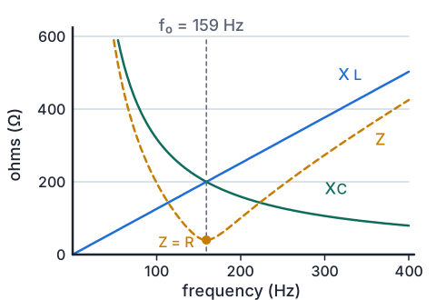
- At one frequency X_L = X_C, so they cancel completely: ωL = 1 ÷ (ωC), which gives f₀ = 1 ÷ (2π√(LC)).
- At f₀ the impedance is just R, its smallest value, so the current is largest and is in phase with the supply voltage.
- Below f₀, X_C is bigger and the circuit behaves like a capacitor (current leads); above f₀, X_L is bigger and it behaves like an inductor (current lags).
- V_L and V_C can each be much larger than the supply voltage at resonance. A radio tuner varies C until f₀ matches one station, so only that station drives a large current.
Try it: reactance and resonance (C in μF)
Example: finding resonance
- A 40.0 Ω resistor, a 0.200 H inductor and a 5.00 μF capacitor are in series with a 6.00 V rms supply of variable frequency.
- Find the resonant frequency, the current at resonance and the voltage across the inductor then.
- f₀ = 1 ÷ (2π√(LC)) = 1 ÷ (2π√(0.200 × 5.00 × 10⁻⁶)) = 1 ÷ (2π × 1.00 × 10⁻³) = 159 Hz
- at f₀, Z = R = 40.0 Ω, so I = 6.00 ÷ 40.0 = 0.150 A
- X_L = 2π × 159.2 × 0.200 = 200 Ω, so V_L = 0.150 × 200 = 30.0 V
- X_C = 1 ÷ (2π × 159.2 × 5.00 × 10⁻⁶) = 200 Ω, equal to X_L
- 159 Hz; 0.150 A; 30.0 V across the inductor, five times the supply
What Achieved, Merit and Excellence look like
- Achieved states the trend; Merit explains it with reactance; Excellence links frequency, reactance, impedance, current and phase, with the physical reason.
- Say which quantity depends on frequency and which does not before you say what happens.
| Grade | A model answer |
|---|---|
| Achieved | The current increases as the frequency increases. |
| Merit | X_C = 1 ÷ (2πfC) falls as f rises, so the impedance √(R² + X_C²) falls and the current I = V ÷ Z rises. |
| Excellence | At higher frequency the capacitor charges and discharges more often each second, so more charge flows and its reactance X_C = 1 ÷ (2πfC) falls; R does not change. The impedance √(R² + X_C²) falls towards R, so the current rises towards V ÷ R. The current always leads the supply voltage, but the lead angle, tan φ = X_C ÷ R, shrinks towards zero as the resistor takes more of the voltage. |
Common mistakes
- The supply voltage is 7.28 + 9.54 = 16.8 V.V_R and V_L are 90° out of phase, so they add as phasors: √(7.28² + 9.54²) = 12.0 V.
- Mains is 230 V, so the voltage never goes above 230 V.230 V is the rms value; the peak is 230 × √2 = 325 V.
- In an inductor the current leads the voltage.In an inductor the voltage leads the current by 90°; in a capacitor the current leads.
- X_L = fL = 50.0 × 0.500 = 25.0 Ω.X_L = ωL = 2πfL, so it is 157 Ω; leaving out 2π is a common slip.
Tune a radio by resonance
You need: a battery radio with an AM band, AA batteries, paper and a pen, a calculator
- Switch the radio to AM and turn the tuning dial slowly from one end of the band to the other, noting the frequency (in kHz) of every station you can hear clearly.
- Notice how a station fades in and out over a narrow range of the dial: that is the resonance peak of the tuner's LC circuit.
- Many AM tuners use a coil of about 250 μH. For each station, work out the capacitance needed, C = 1 ÷ (4π²f²L), with f in hertz.
- Compare your values for the lowest and highest stations.
- Look for: the highest station needs the smallest capacitance, because f₀ is proportional to 1 ÷ √C; the tuning dial turns a variable capacitor to change C.
Safety: Use only a battery radio with AA cells, and do not open the case or try this with a mains-powered set, because mains voltages inside can kill.
Your turn
Find the peak voltage of a 12.0 V rms AC supply.
Find the reactance of a 0.0500 H inductor at 1000 Hz.
A 1.00 kΩ resistor and a 2.20 μF capacitor are in series with a 10.0 V rms, 100 Hz supply. Find X_C, the impedance and the current.
An AM tuner has a 250 μH coil and a 177 pF capacitor. Find its resonant frequency.
Show answer
1. V_max = √2 × 12.0 = 17.0 V. 2. X_L = 2πfL = 2π × 1000 × 0.0500 = 314 Ω. 3. X_C = 1 ÷ (2π × 100 × 2.20 × 10⁻⁶) = 723 Ω; Z = √(1000² + 723²) = 1234 Ω, about 1.23 kΩ; I = 10.0 ÷ 1234 = 8.10 × 10⁻³ A (8.10 mA). 4. f₀ = 1 ÷ (2π√(250 × 10⁻⁶ × 177 × 10⁻¹²)) = 7.57 × 10⁵ Hz, about 757 kHz.
Exam-style question: a series LCR circuit
- In a school lab, a 50.0 Ω resistor, a 0.150 H inductor and a 22.0 μF capacitor are connected in series to a 6.00 V rms supply whose frequency can be varied.
Calculate the resonant frequency of the circuit.
Calculate the rms current at resonance.
Calculate the rms current when the frequency is 50.0 Hz.
At 50.0 Hz, state whether the current leads or lags the supply voltage, calculate the phase angle, and explain why.
Show answer
1. f₀ = 1 ÷ (2π√(0.150 × 22.0 × 10⁻⁶)) = 1 ÷ (2π × 1.817 × 10⁻³) = 87.6 Hz (Achieved). 2. At resonance X_L = X_C, so Z = R = 50.0 Ω and I = 6.00 ÷ 50.0 = 0.120 A (Merit with the reason). 3. X_L = 2π × 50.0 × 0.150 = 47.1 Ω; X_C = 1 ÷ (2π × 50.0 × 22.0 × 10⁻⁶) = 144.7 Ω; Z = √(50.0² + (47.1 − 144.7)²) = 109.6 Ω; I = 6.00 ÷ 109.6 = 0.0547 A (Excellence for the full calculation). 4. Below resonance X_C is larger than X_L, so the capacitor's voltage outweighs the inductor's and the circuit behaves as a capacitor: the current leads the supply voltage. tan φ = (X_C − X_L) ÷ R = 97.6 ÷ 50.0, so φ = 62.9°. On the phasor diagram the net reactive voltage points down, so the supply voltage lies below the current phasor (Excellence links the reactances to the phase).
Recap
- V_rms = V_max ÷ √2: NZ mains is 230 V rms, 325 V peak, 50 Hz.
- Resistor: V and I in phase. Inductor: V leads I by 90°. Capacitor: I leads V by 90°.
- X_L = 2πfL rises with f; X_C = 1 ÷ (2πfC) falls with f.
- Series voltages add as phasors: Z = √(R² + (X_L − X_C)²) and V = IZ.
- Resonance when X_L = X_C, at f₀ = 1 ÷ (2π√(LC)): Z = R, maximum current, V and I in phase.
| Formula | Use it for |
|---|---|
| V_max = √2 V_rms | peak and rms |
| X_L = ωL, X_C = 1 ÷ (ωC) | reactance |
| Z = √(R² + (X_L − X_C)²) | impedance of a series circuit |
| V = IZ, tan φ = (X_L − X_C) ÷ R | current and phase angle |
| f₀ = 1 ÷ (2π√(LC)) | resonant frequency |
The maths behind it
Report a mistake
How is NCEA Level 3 maths going?
See the NCEA Level 3 maths guide